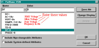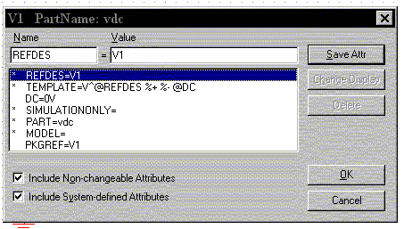
V 2 is the value when the pulse is fully turned on.For a pulsed current source, the units would be 'amps' instead of 'volts.' V 1 is the value when the pulse is not 'on.' This can be zero or negative as required.The parameters for the pulse (to be entered in the order given) are: An example of a pulse type of voltage source follows: Items in the parameter list may be separated by spaces or commas. Then, instead of 'DC' or 'AC,' we use the keyword 'PULSE' followed by the necessary parameter list. The designation of the pulse source starts as any other independent source i.e., the part name must begin with the letter V (for voltage) or I (for current). It should never be used in a frequency response study because the model assumes it is in the time domain. We often use it as a stimulus for transient response simulation of a circuit. This type of source can be either a voltage or a current source. This by no means completes the list of possible sources in PSpice, but these new sources will add a great deal of capability to our circuit modeling efforts. At this time, we will introduce three new independent source types and two new dependent source types. These include the independent DC and AC voltage and current sources, and the simple voltage or current controlled dependent voltage and current sources. Up to now, these tutorials have discussed only the most basic types of sources. Available at no cost, PSpice for TI includes one of the largest model libraries in the industry, spanning our analog and power portfolio, as.


This full-featured, design and simulation suite uses an analog analysis engine from Cadence®. PSpice® for TI is a design and simulation environment that helps evaluate functionality of analog circuits. PSPICE Schematic Note that the pulse parameters are set to be: TD = 0 (no delay, start the pulse train at t = 0) TR = TF = 1n (10-9 makes the rise and fall times almost zero) V1 = 0 (pulse starts at zero) V2 = 1 (rises to one volt) PW = 1 (pulse width is 1 second). The PSPICE schematic for this circuit is shown in figure 3.

This tutorial assumes that you are running OrCAD 16.2 Demo, the most recent demo version. It will take you through the steps of entering a schematic diagram, specifying the type of analysis, running the simulation, and viewing the output file. PSPICE Tutorial 1 PSPICE Basics Introduction This tutorial will introduce Orcad PSPICE.


 0 kommentar(er)
